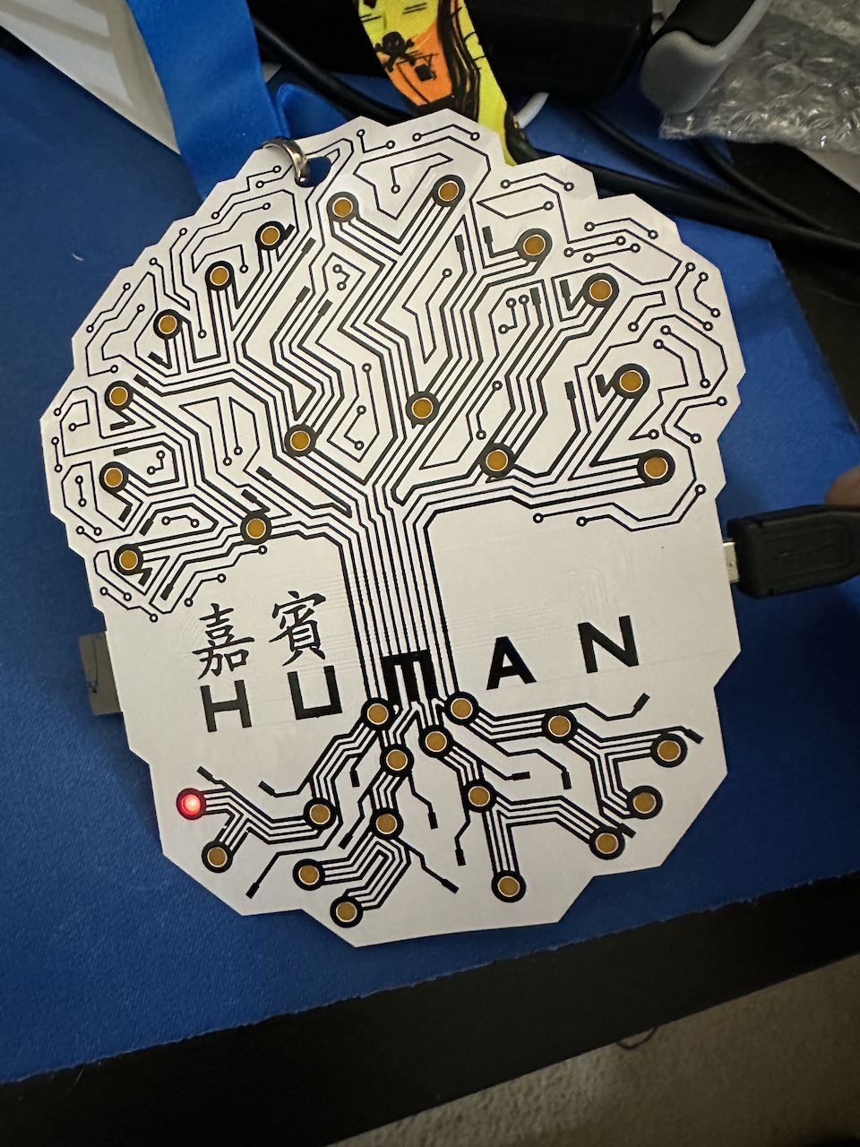
The Defcon China 1.0 Badge is an interesting piece of history. This is the first flexible circuit board badge used by the Defcon conference.
![]()
From watching the interviews and background, circuit design changes were made to enable a flexible board. One issue in the prototypes phase was the potential for pins to bridge between chips when bending. You can’t just make a flexible board with the same design as usual, so components were spaced out and pins are placed where they can’t reach each other.
![]()
As for the board challenge, they wanted to encourage attendees to visit different villages and sections of the conference, in order to set flags on the badge unlocking specific LED lights. Some of these flags are enabled by directly interacting with the badge, but most are intended for village unlocks.
This is the process I used to fully unlock my badge without being at the conference.
First off, I like to do things on the console as much as possible, so for finding the USB serial device when plugged in I use this:
% ls -lt /dev/cu*|head -n 1
crw-rw-rw-  1 root  wheel  0x9000007 Jan 13 15:23 /dev/cu.usbserial-DC0622A2
Then screen with the new device where I’ll try a few common baud speeds til I get the text decoding correctly. In this case it’s 9600 which will be important later.
% screen /dev/cu.usbserial-DC0622A2 9600
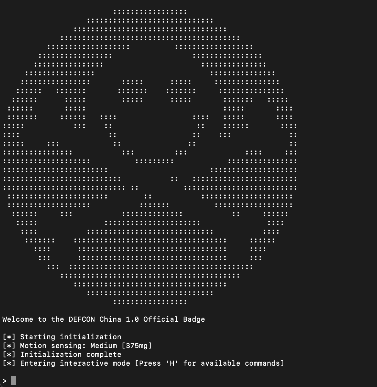
Believe it or not the first flag is simply using the USB serial interface and sending a single command. As soon as I sent an “H” I got my first LED lit up.
![[*] Flag: Badge connected to computer output](/images/defcon_china_first_flag.png)
You can see highlighted at the bottom the very first game flag is now active.
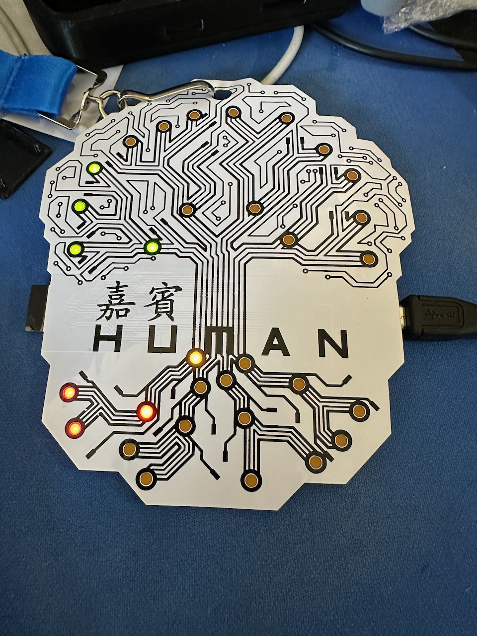
Now the way they use the game flags is that each root in the tree is 4 flag bits, for each batch of unlocked root nibbles you’ll light up the corresponding green branch above.
I tried every key and no hidden menu items were found, with not much else to do after playing around with the menu I started digging through the code. This badge is running an Arudino platform with it’s INO files which are basically a custom version of C++.
Looking around at the released badge code I first noticed the #define nSolderBlob… that looks like a fun one. Going to it’s use we find that briding pins 9 and 10 will enable this flag.
    // If ATmega328P pin 9 (D5, ROW2) is connected/soldered to pin 10 (D6), nSolderBlob will go LOW during LED multiplexing
    if (!digitalRead(nSolderBlob) && !bitRead(b9, 1))
    {
        printProgStr(msg_flag_solder_blob);
        bitSet(b9, 1);  // update flag
        EEPROM.write(EEBaseAddress + 9, b9);
        pinMode(nSolderBlob, INPUT); // re-configure pin as an input (without pull-up)
    }
Let’s find those pins…. ATmega328p pins Alright so D5 and D6 are physical pins 9 and 10 in the bottom left corner when viewing the chip text right side up.
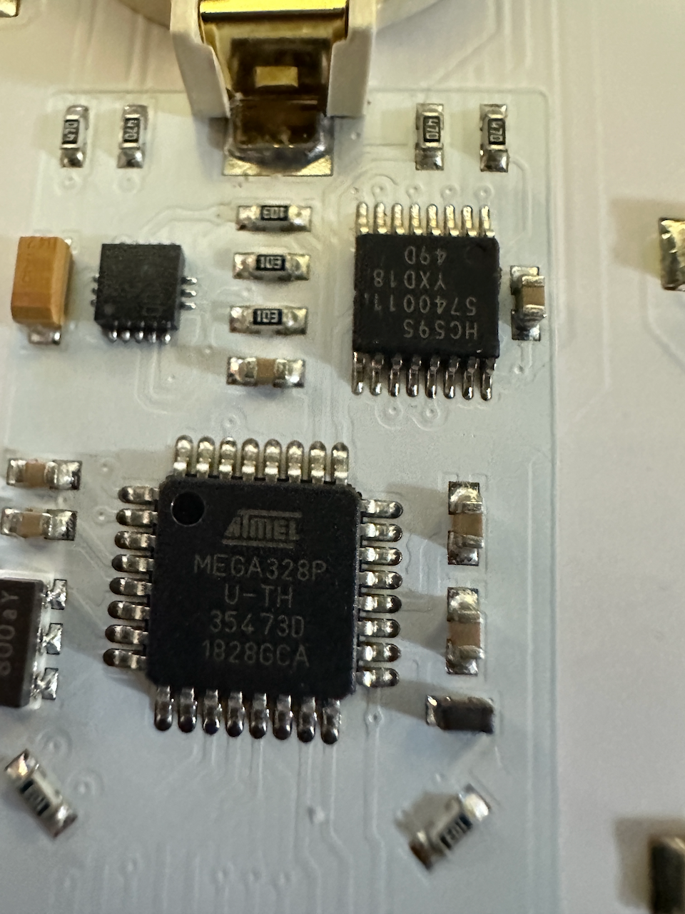
Bridging these with a needle I got the 2nd light on.
![[*] Flag: Solder blob output](/images/defcon_china_solder_blob.png)
Now that I’ve seen ‘bitSet’ it’s easy to go find the other places that turn on other flags. What else can we find?
    // If you took the badge hacking workshop (or otherwise found the #define)
    if ((ATTENDED_BADGE_HACKING_WORKSHOP == true) && !bitRead(b9, 2))
    {
        printProgStr(msg_flag_badge_hack);
        bitSet(b9, 2);  // update flag
        EEPROM.write(EEBaseAddress + 9, b9);
    }
The badge hacking village workshop! That makes a lot of sense. Those 3 flags are the only ones that are specific to a known activity, all the rest were set in person by finding badge stations placed throughout the conference. What we find is that the badge stations each set a specific bit in the flags by sending a UART command very similar to the menu commands. These commands are “S” for set a bit, R to read the bits and C to clear a bit.
This post is getting a bit long, so let me show a fully lit root and branch once the first 4 bits are set.
Next up I’ll dig into a custom firmware and LED stuff I learned from this.