Okay now a little side journey I took during this. In part two you might have noticed my snazzy badge back. This was a quick 3D model I made to protect the badge since it’s getting a little beat up during #badgelife sessions bumping into other badges and I’m using the USB connector a lot. Feeling a bit concerned that I’d rip it off eventually IMO this badge needs more backbone. I’m briefly sharing my process so anyone with a printer can get some super simple design going and gradually improve them with practice.
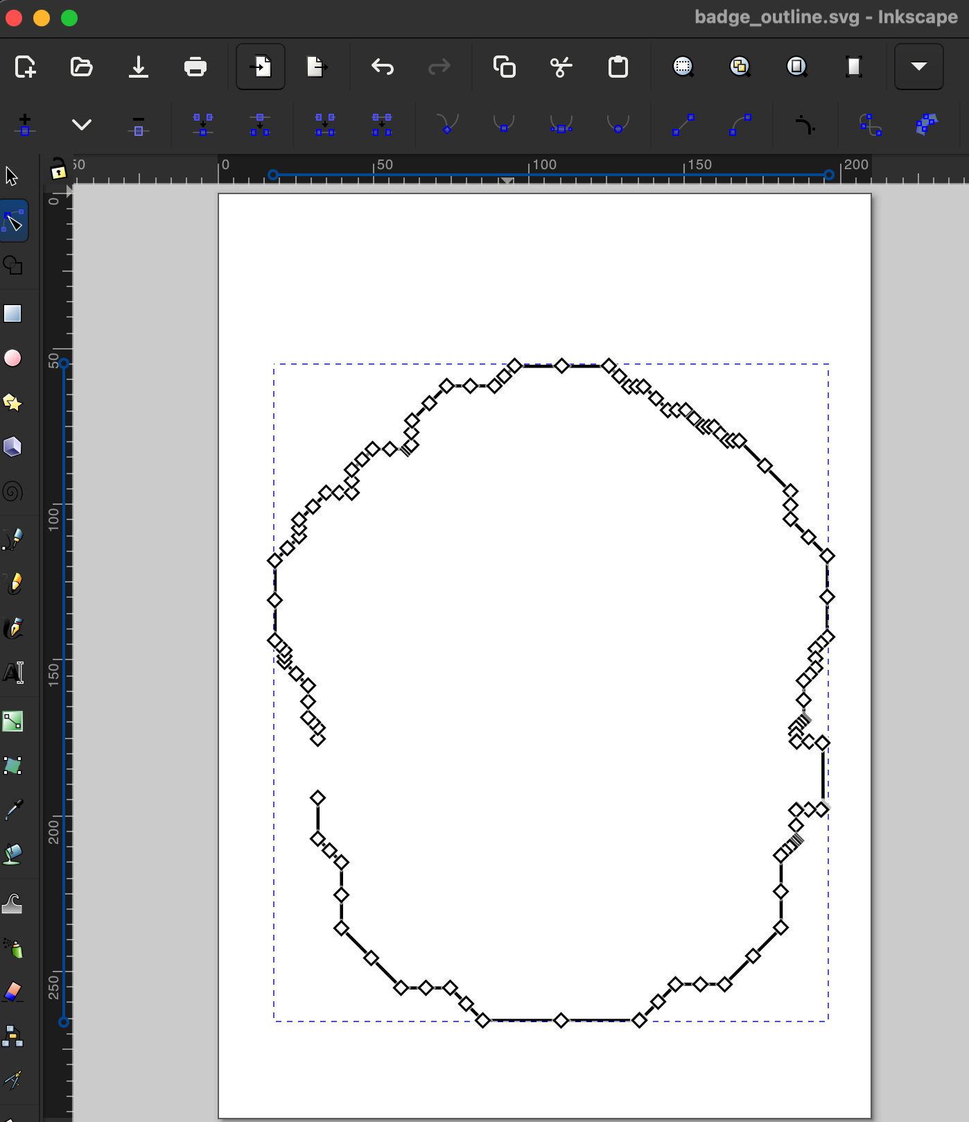
There’s a lot of better modeling tools but I’ve got a process that works for me in PrusaSlicer. First off I attempted to use the badge design PDF from the Defcon media server (inside the badge files rar archive). Importing it into Inkscape, that badge outline didn’t end up giving me a nice clean vector, instead it ended up being 17k tiny little unconnected line segments.
![]()
💥
Attempting to combine them and simplify on the path didn’t work for me so after fighting with it a while I just used the badge back JPG and did a trace bitmap. Lame but it worked. I ended up with a nice clean line with only 127 nodes.
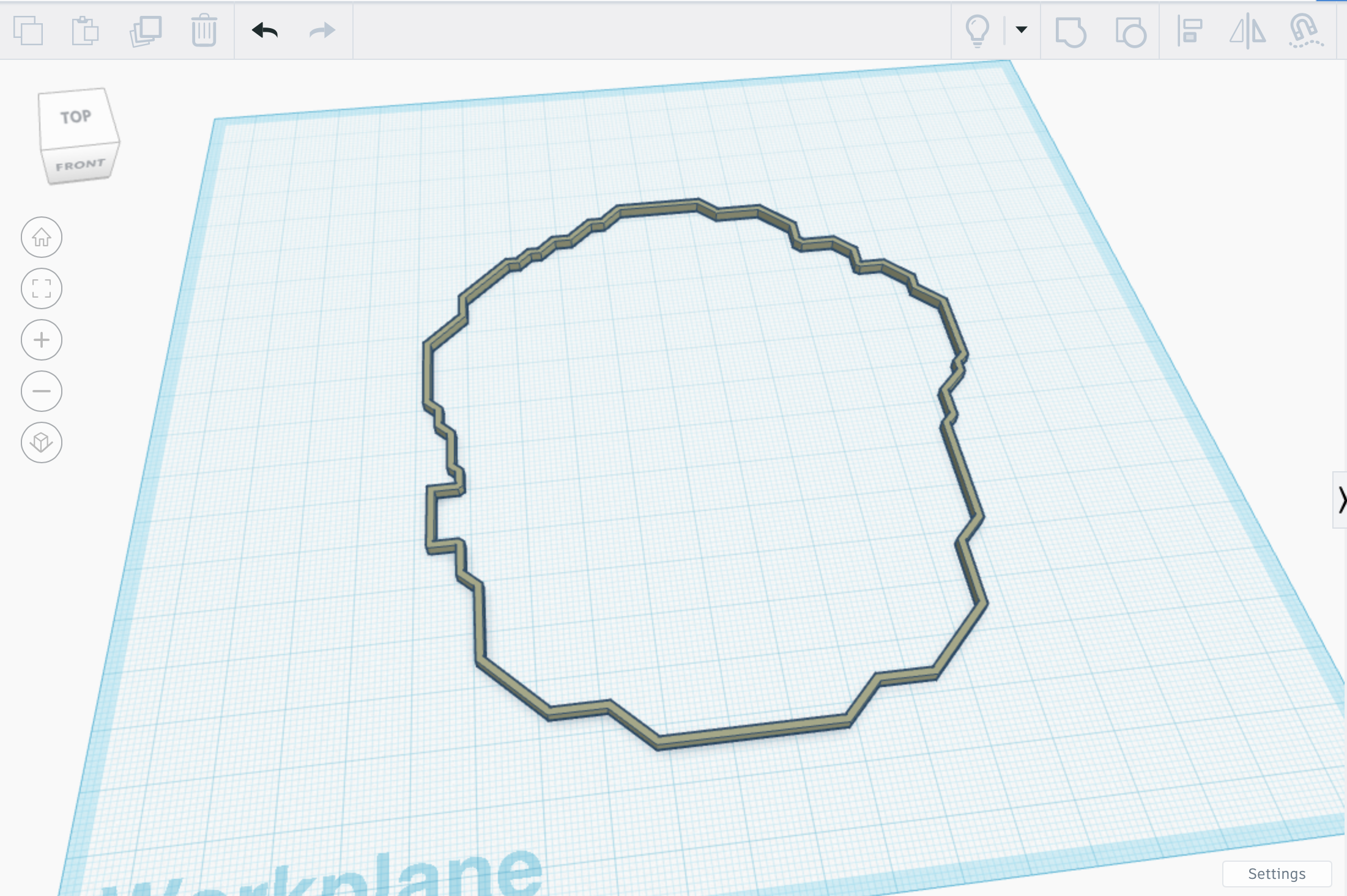
From there I turned it into the rough outline shape in Tinkercad and that was the base of my model in PrusaSlicer.
A quick tip on making an inner and outer perimeter, you can’t simply copy a path and increase it by 5% to make a wrapped shape. The outer ring is actually a different shape and if you only enlarge the inner shape you’ll end up with gaps.
![]()
The trick is using Inkscape and the Path > Outset function. This truly gives you a perfect fit outer track that you can use for a surrounding wall as I’ve done for the badge edge.
Back to PrusaSlicer, with a working initial shape, I then just right click on an object and use Add Part > Box slowly adding on clips and hole backing as I need it, modifying with negative modifers such as the hole and USB punch outs. Also I name the objects along the side so it’s easy to find the parts I want to adjust.
![]()
I then export the plate to STL, and import it to a new project. The reason is, the slicer will attempt to print each object even if they’re overlapping, you can see the difference in these screenshots. Notice double the external perimiter print time when it’s discrete objects. Also see the G-code path error.
![]()
![]()
Having overlapping parts in the print path causes cascading collusions where plastic already exists and neither part is compensating for the quickly growing blob that eventually destroys the whole print. So the export to clean it up step is necessary.
Oh…. uhhh…. prototypes. Tweak as you go, sooner or later it’s done.
![]()
“Why didn’t you just do all the modeling in Tinkercad?” … :| .. That’s a very good point.
Personally I gravitate to open source solutions even when they’re sub-optimal. In future projects I’ll be trying to remove any dependency on closed source steps.
I also added a lobster clasp line because the lanyard clip for this badge is pretty strong and I didn’t want to bother getting it to fit in the hole, it’s already almost ripping the badge as is. Alright…. black or red, which looks better with this badge?
![]()
(How I am I so wise in the ways of lobster lanyards?)
![]() Source
Source
I ended up with short lanyards for the DC32 badge I got, so looking around I found some longer replacements and picked up 2 packs for extremely cheap.
So “lanyard lariat lobster clasps” got me finding the right stuff, and you want the 70mm end to end length for the DC32 badge to comfortably loop the loose way. Guess I have a lifetime supply now, I’ll add them to any badges I have with iffy connections or where the clip is rubbing into the PCB.