I was super excited to finally aquire a much coveted AND!XOR 31 badge. Through searches and archive hunting I’ve learned that there was an early access kickstarter type pre-sale which partially funded the free badges they gave away in the 5n4ck3y vending machine. Some of those pages are no longer around but I’ve found there was at least 3 badge front plates, the wooden which I have, and a diamond and metal for various sponsor levels.
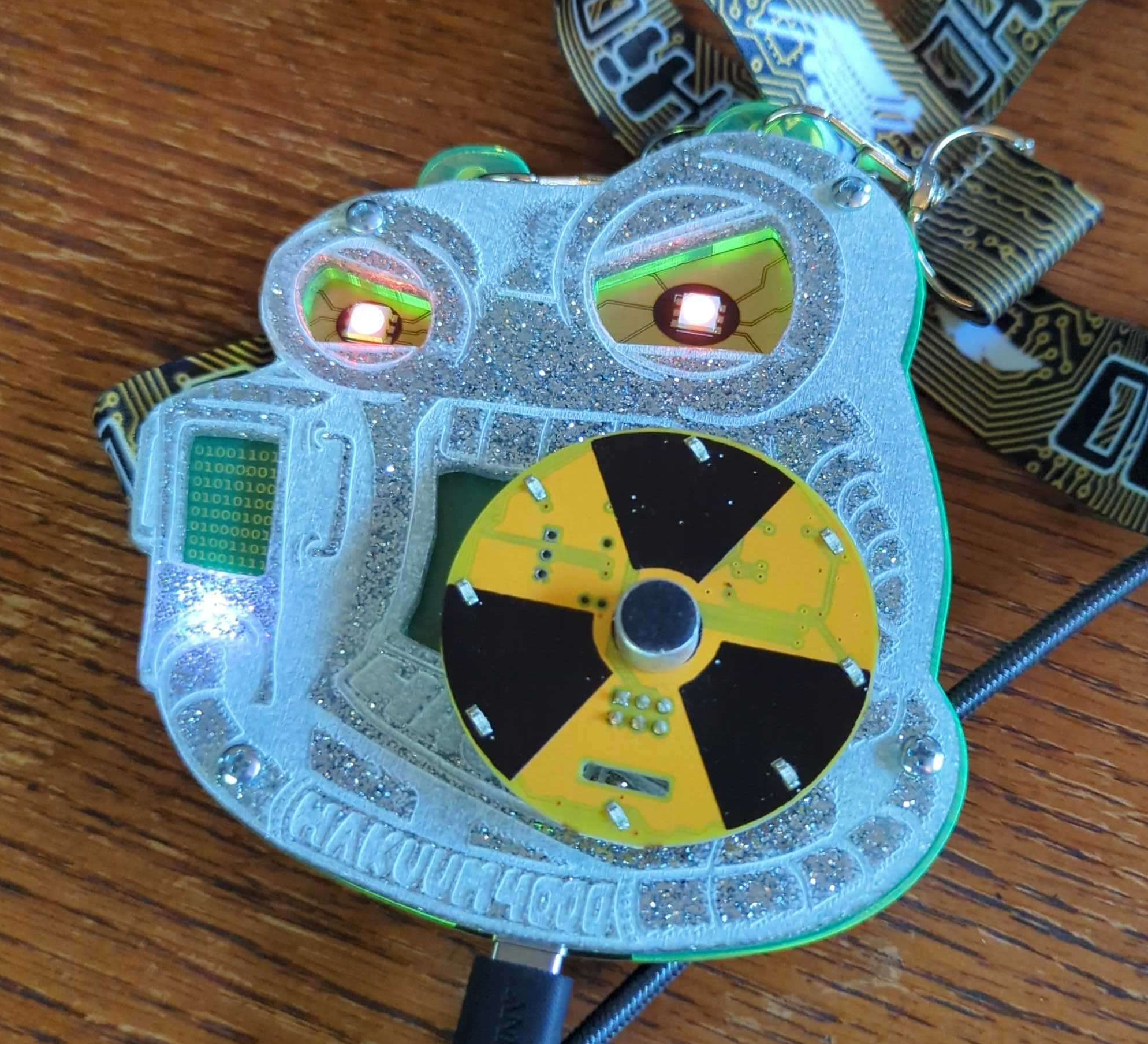
The diamond (Glitter in resin then CNC’ed?)
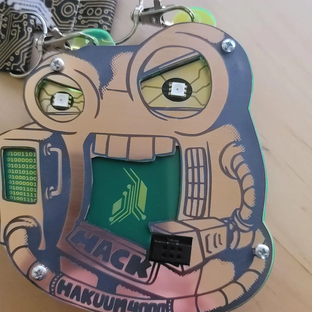
The copper (Bare circuit board with black mask?)
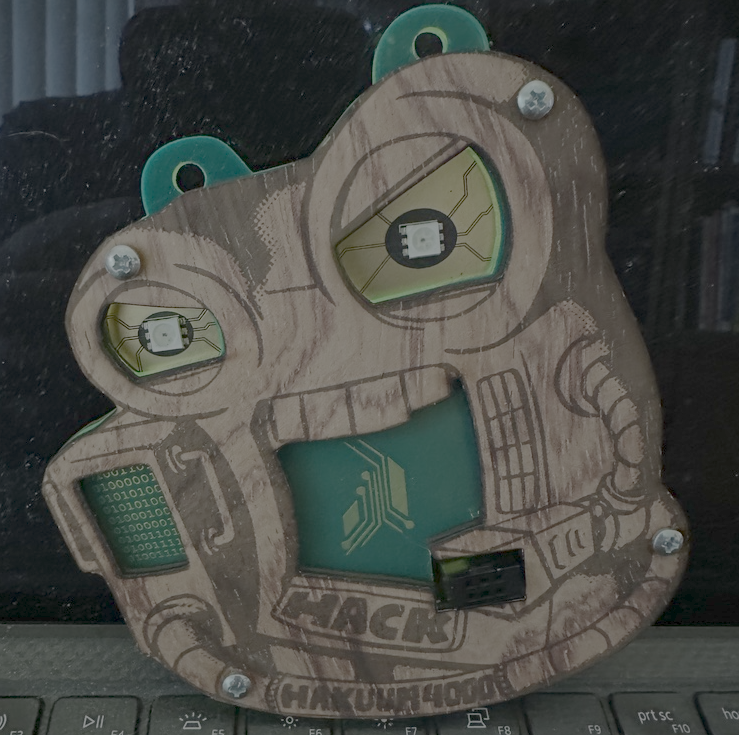
The wood (Laser cut and engraved)
I vaguely feel I saw once a set that included multiple swappable front plates. What a nice way to incentivize the sponsors…. which they called…. philanthropists. 🧐
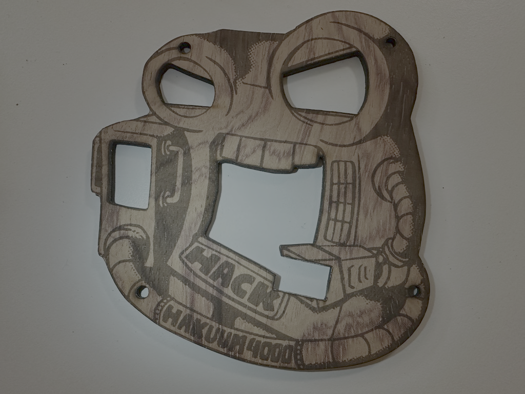
Tracing the badge front
Sharing my mistakes to save you a lot of time. The github repo for this badge was missing so I didn’t have any vector source or a nice clean image, my first attempts were with a cell phone camera photo of the badge.
 It seems well enough eh? But I quickly ended up making many single layer prototypes and manually adjusting the badge outline by eye. Not a great method, but I felt I was making progress and continued.
This is a huge waste of time. Don’t do it that way. If you must, you must. But if you have access to a flatbed scanner, that’s the way to do it. The phone camera is never going to be lined up correct, there’s lens distortion plus not being perfectly centered over it, additionally the camera lighting is going to make a lot of shadows that are hard to separate from the edge.
Scan it. Drop it in Inkscape.
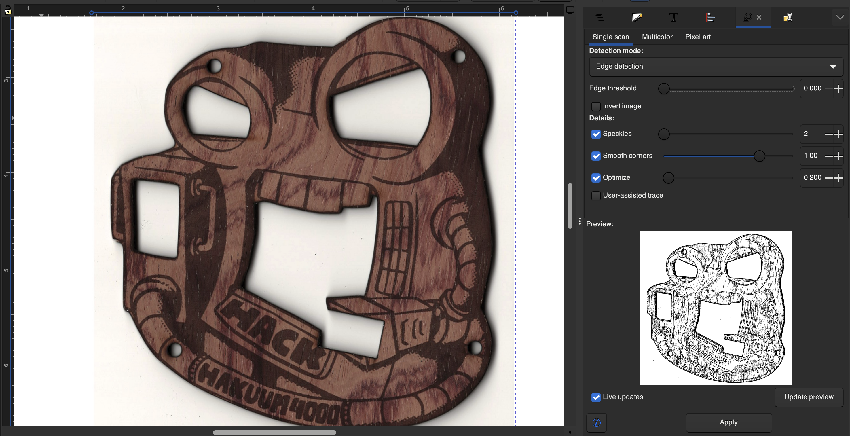
Now let me save you more time here.
When doing trace bitmap, break it into two separate shape layers. Just duplicate the trace if you need, or do two traces with different settings, one for the outline, the other for the details.
When you work on one, lock the other and make it invisible. You want a nice clean outline of the entire object, then separately the detail layer that we’re going to use for a color swap later.
In this case the wood grain made the tracing pretty difficult. I started to get fairly comfortable with the node tool and moving along with some decent speed.

Cleanup
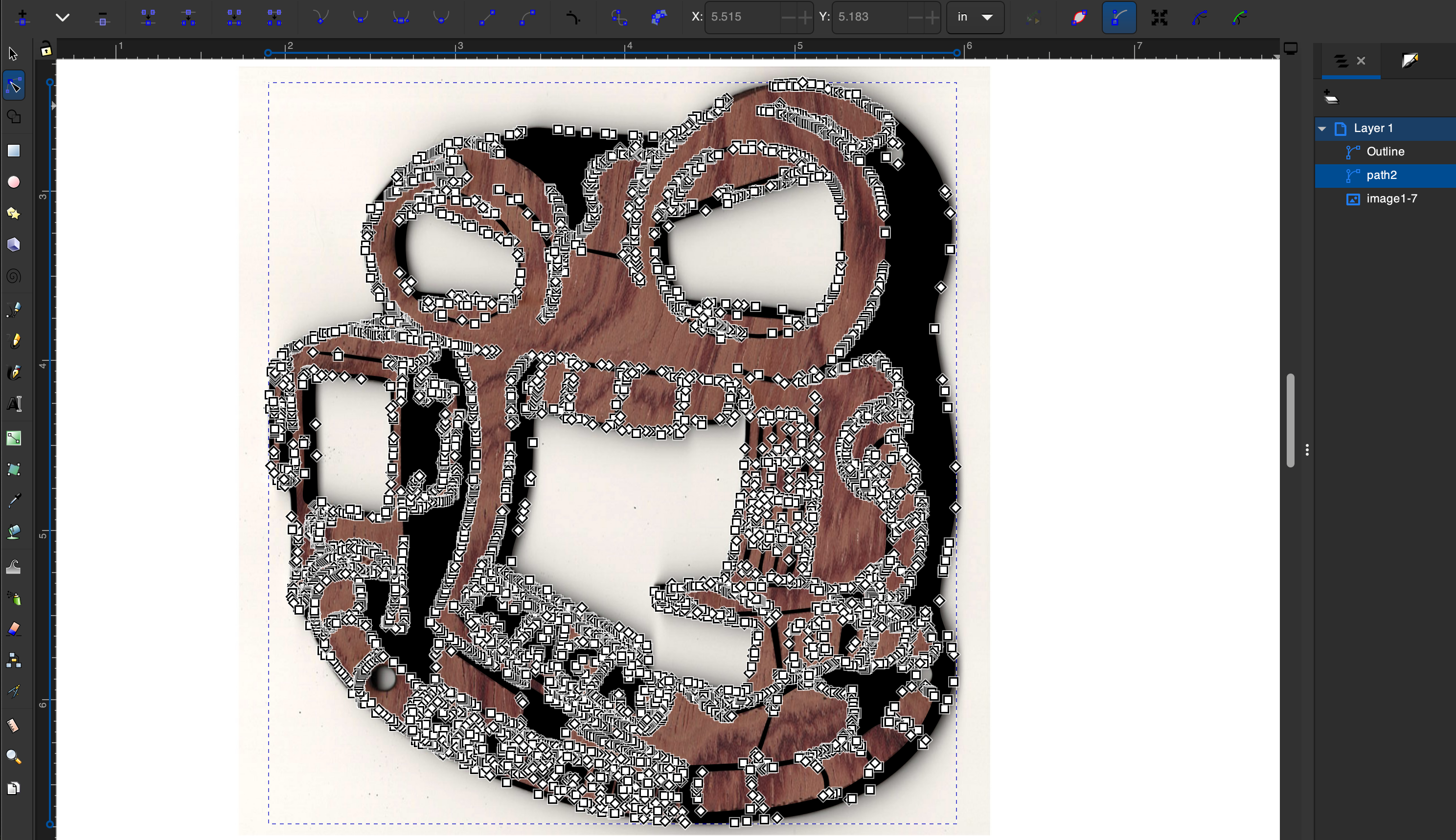
Alright for 3d printing we want to sort of create a reasonable approximate of the original artwork, and make something that prints well. This means removing speckles, tiny dots and joining line gaps. We’ll want to widen some lines so they print intact, and also remove wobbly lines that simply cause a ton of micro-adjustments but provide no actual value. Smoothen those curves, simplify edges.
Quick node edit tips:
Easily Split shapes The split segment node tool will not work on a “looped” line. When we trace a pen stroke in Inkscape we’ll end up with a shape object resembling the original line. The Split segment tool words on a line segment, however this is a filled path. So to divide two smudged lines, add a nice eliptical between them, while it’s selected return to the node tool, hold shift, click the nodes, now use Path > Difference to boolean subtract the shape from the nodes. This will cleanly break apart the objects close to how we want them.
Delete, delete, delete. A curved line with 200 nodes is not going to print well. Using the node tool I grab a large chunk and just delete around 90% of the nodes. Leave the ones on the end that could define the curve sufficiently by themselves, delete the rest. If the handles fly out somewhere crazy, just grab each one and move it halfway along the distance towards the other node, and do the same for the opposite handle. There you go, the curve is fixed.
(Unhelpful level of detail)

Gapped line segment objects. For a badly scanned line, the easy way to join is grabbing the last 2 or 3 nodes on one end, and then dragging them into the next segment. Then use Path > Union to make a single object. That’s it. I’ll usually just grab the whole section and delete a ton of nodes right after joining, it’s then nice and smooth.
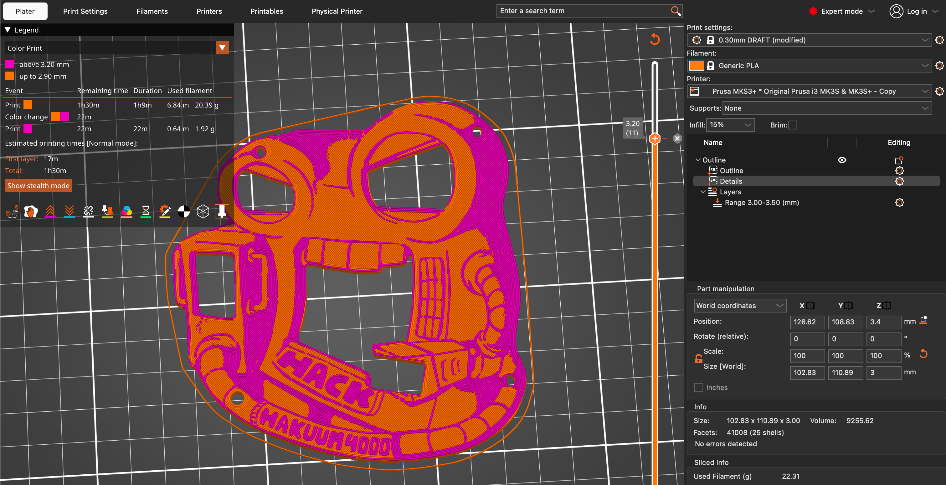
3D modeling
Here’s the best trick I learned doing this. When you drop an SVG file in PrusaSlicer, it only creates a shape out of the visible layer. Since it’s super easy to keep multiple players in sync in a single file, just keep it that way. Make the details layer invisible, and the outline layer visible, drop on the plate. You have a badge shape outline object. Make it 3mm thick. Now back in Inkscape, reverse the layer visiblity and show the details, save. In PrusaSlicer select the badge object, add a part, choose SVG, use the same SVG file. Tadaaaa.
Make the details layer pop up around .30mm higher than the base object, use variable layer height modifer to set the top layers to .10mm thickness. Add a color change break right after the final base object layer. Slice and verify you have 3 or 4 thin layers for the 2nd color.
Boom.
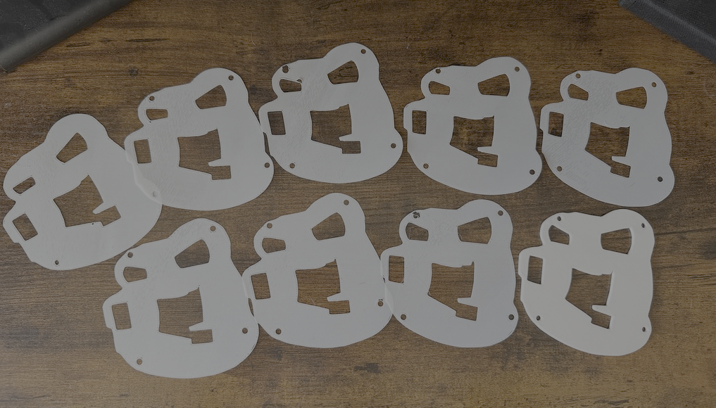
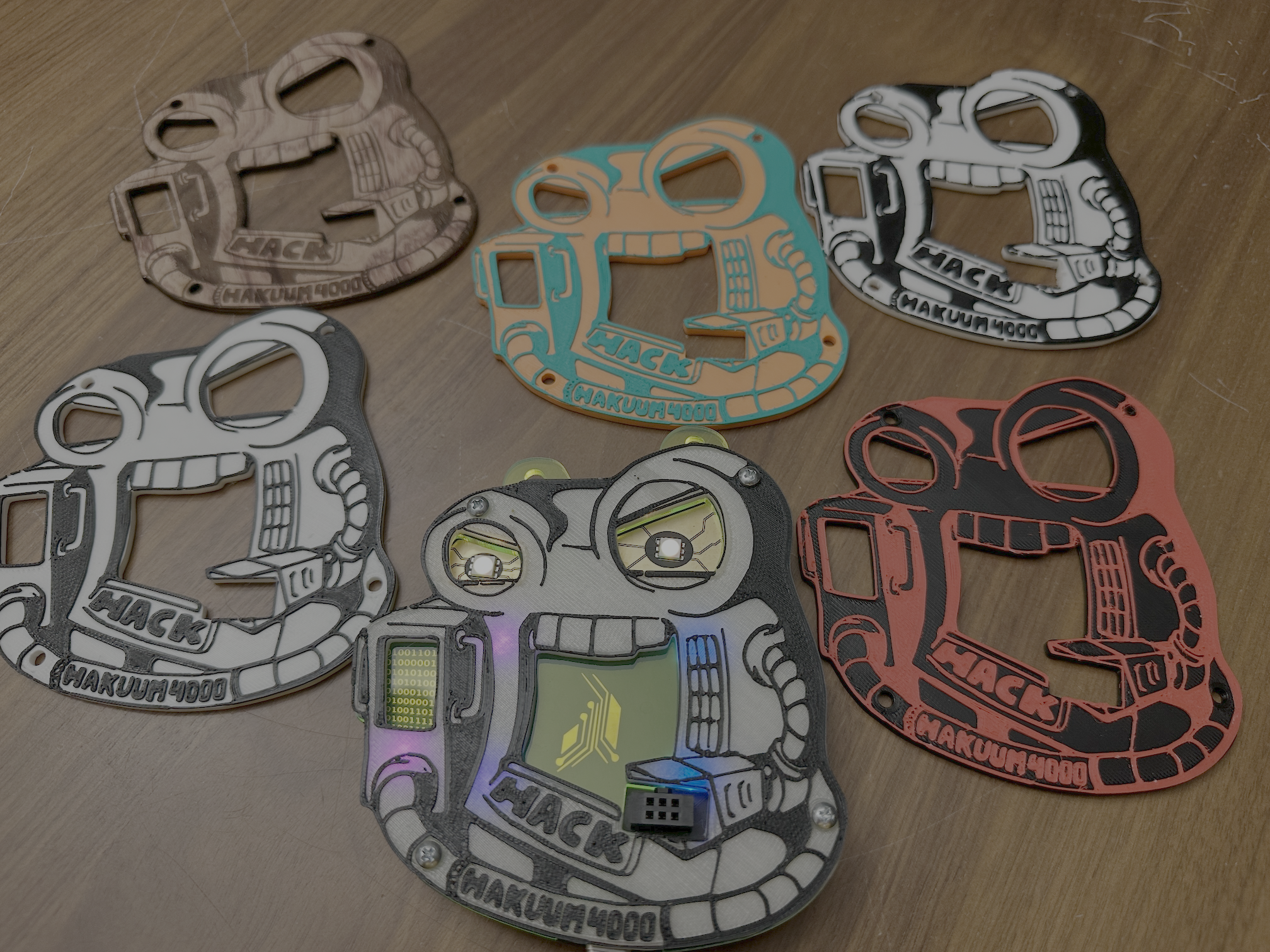
Meet the family
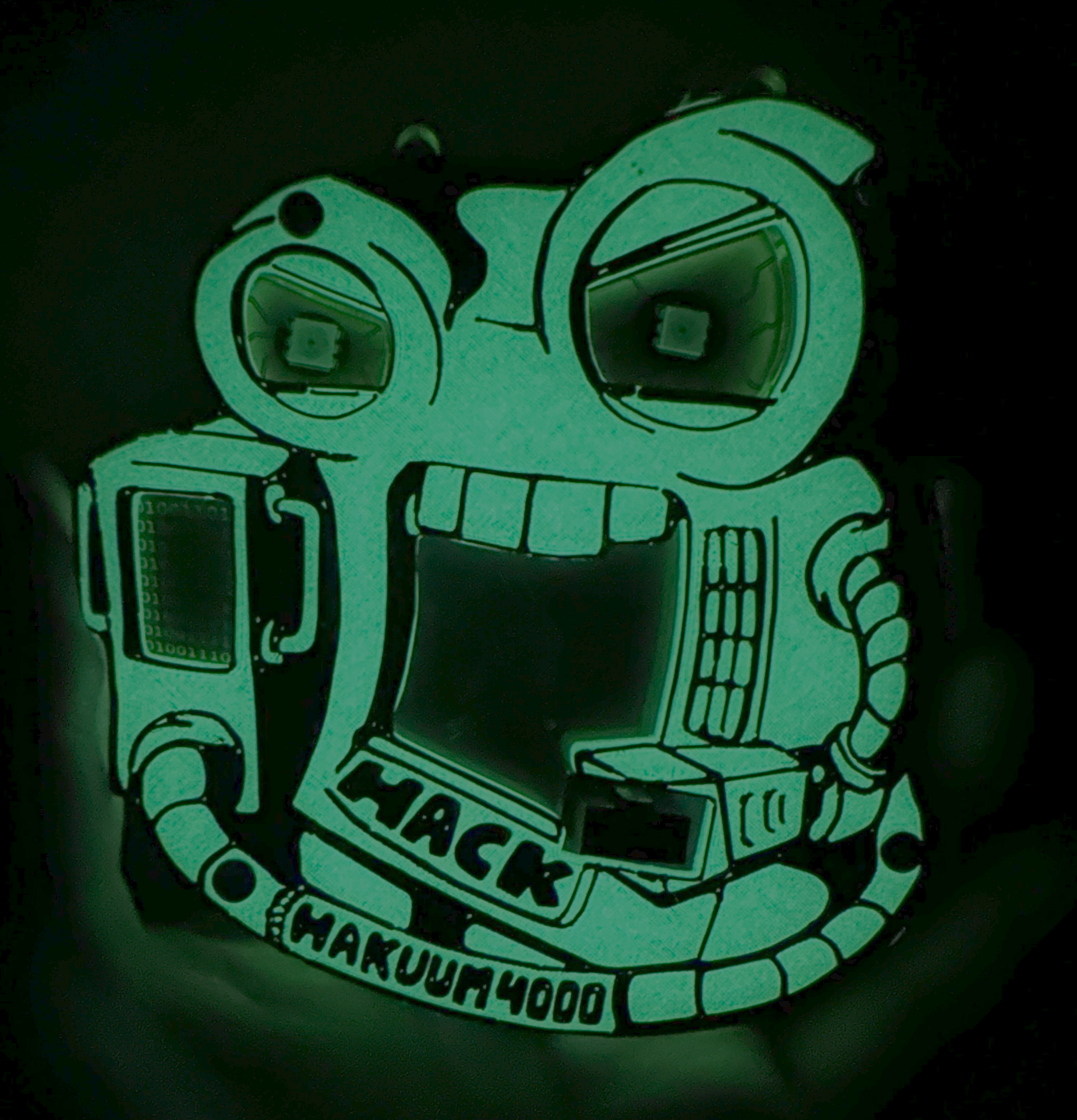
That’s right I glow in the daaaaark!
Thanks to the AND!XOR crew for another amazing badge!