All these badge posts and I’ve never mentioned a solid bedrock for learning electronics skills and basic hardware hacking…. the Hackerboxes collection!
These kits are pretty sweet, nice and curated, just enough of a challenge to stretch a bit, but not get completely overwhelmed. Just…. appropriately whelmed.
They very consistently have a full guide on Instructables, along with a video or two. The Instructables will have some user makes photos at the bottom and some comments with common trip-ups and how they got through things. With a nice set of Hackerboxes you’ll get a full exposure to all the main MCU board types, digital protocols like SPI and I2C, WiFi, Bluetooth, IR, etc, etc…. I mean 10 well chosen boxes will get you far. Each project is a solid foundation with a working example leaving you free to expand and grow from there.
What I do is skim the available kits and snag the ones that interest me, then watch for the older ones on auction sites. Sometimes you can get them cheaper than retail.
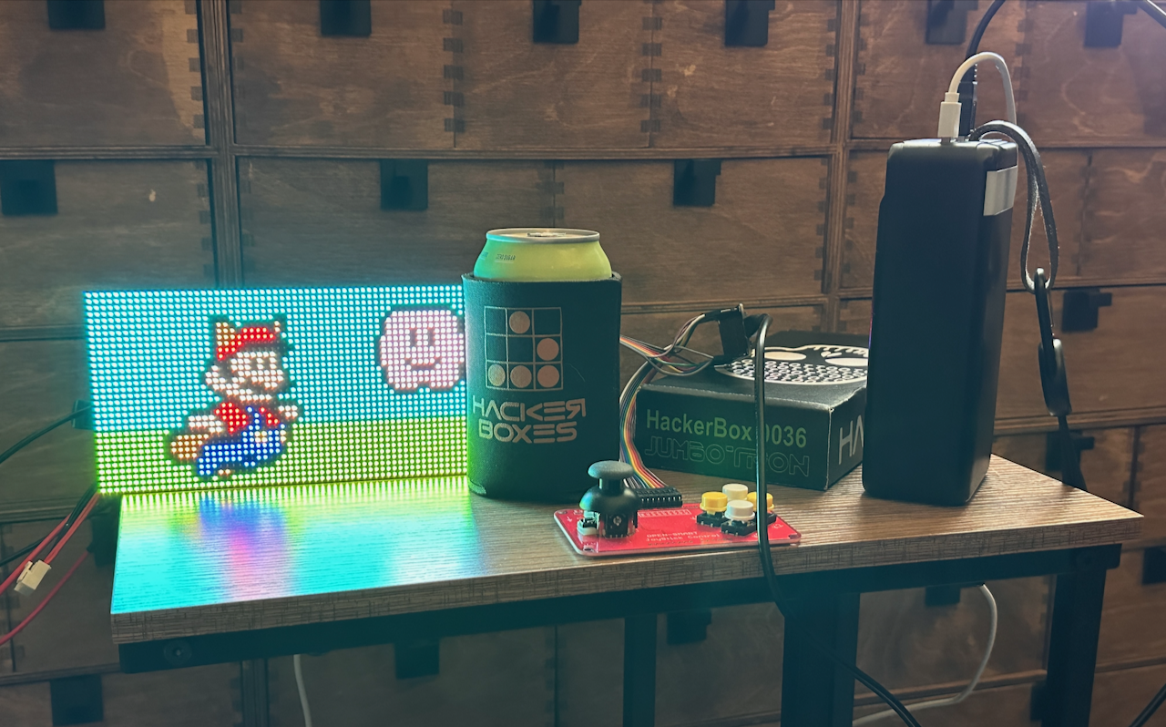
This one is JumboTron Box 36, 7 years old at the moment, and slightly dated with the Micro-USB connector and early generation ESP32 board. It’s all good. Just a wee bit of googling and you’ll be up and running.
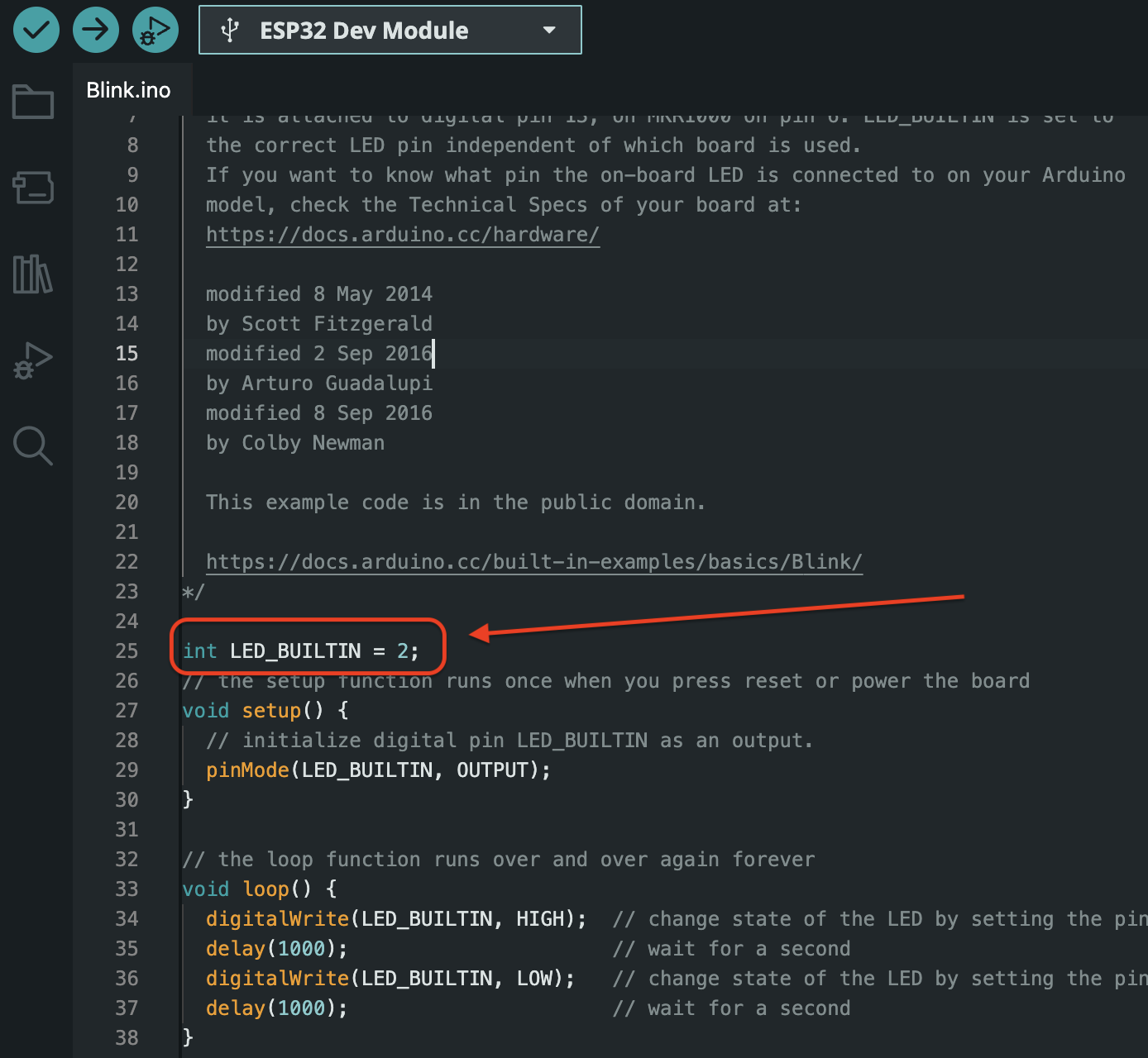
My Arduino skills have slightly atrophied, and some board names have changed over time, this was fairly easy. With the official Expressif github json link added to the IDE per the instructions you only need to look for the “ESP32 Dev Module” and find its port, then for the “Blink” test, on this particular board the built in user control LED is on pin 2. As pictured in the IDE, only this one line needs to be added.
I think beyond that, the older instructions about putting the board in flash mode seem to be superfluous and the IDE was able to flash the board immediately. Funny thing about Arduino compatible boards is all the weird little ways you have to trigger flash mode. Sometimes it can do it for you, other times like with a Digispark you have to time it right with plugging in and flash attempts. You also end up learning niche stuff, for example the ATtiny85s on the Digispark don’t have a USB interface chip. So how does the USB connector work? They use a bit-banged USB protocol in a tiny firmware called Micronucleus. Very cool to learn how they use a itty bitty bootloader and flash the running program on the remaining space, and for the Digisparks when you first plug it in there’s a brief delay while it’s in flash mode before it jumps to whatever is flashed after it. But I digress……….
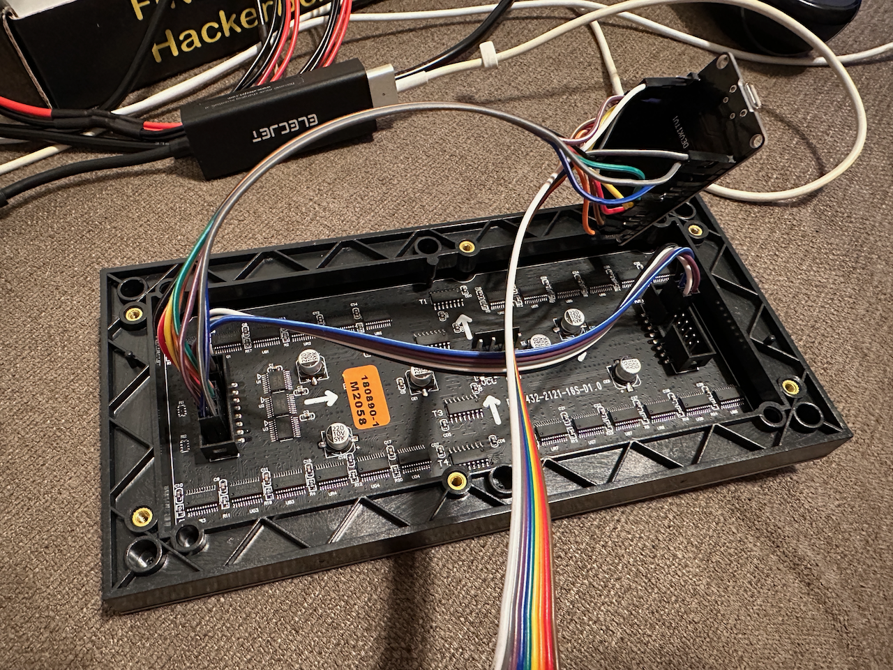
Putting it together.
The pins are pretty close together and it can take some back and forth to figure out which one goes where, but definitely doable. Just be meticulous and careful. Don’t be afraid to peel the wires apart a little further so you have more slack and can move them around more.
Building the software.
Got a build error the first time attempting the demo .INO file. Here’s the error 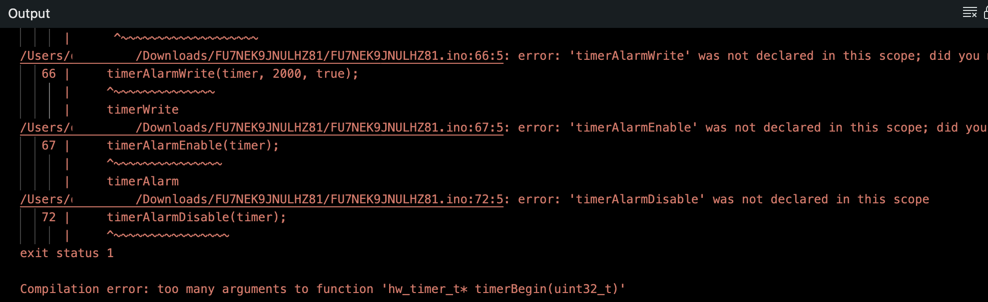 It’s easy to freak out with build errors, but pay careful attention to the last line. “Too many arguments to the function……” usually this indicates a compatibility issue. Further up in the error chain I see it complaining about no GPIO definition. That’s pretty odd as well. It turns out the PxMatrix library is built for an older Arduino core, the GPIO handling changed with 3.0, so downgrading it to a 2.0 series should clean up that error.
Using the Board Manager to install the latest 2.0 version of the ESP32 board….
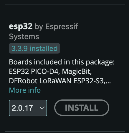
That fixed the build issue. Sweet!
Does it work right on the first try?
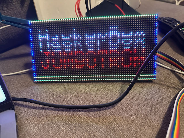
That’s pretty close!
Checking for loose connections I had one pin dangling loose… getting it back in all the way and… boom!
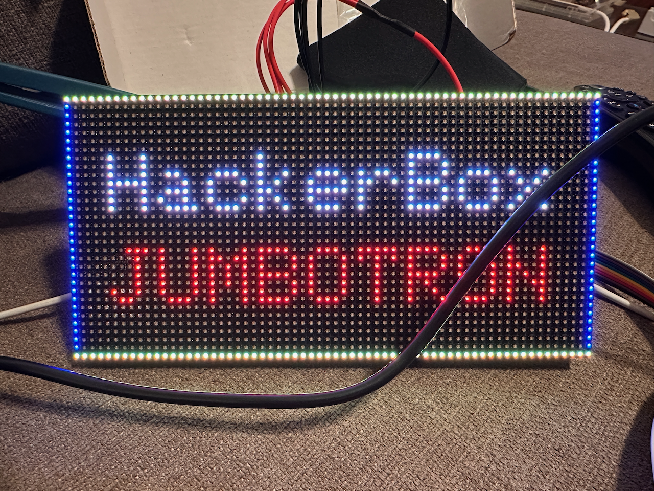
Next up, let’s try Mario.
Fixing the error by simply adding “_t” on the type declaration. (Old obscure Arduino type definition history….)
It builds! But looks like…
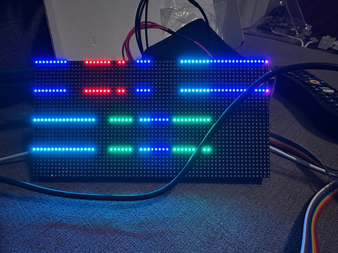
I mean it’s a whole different project and the pin definitions are sort of randomly mixed up…. let’s just sorta copy them across and maybe it’ll work. If not I’ll figure out their R1, R2, G1, G2 to A, B, C, D stuff… this could work.
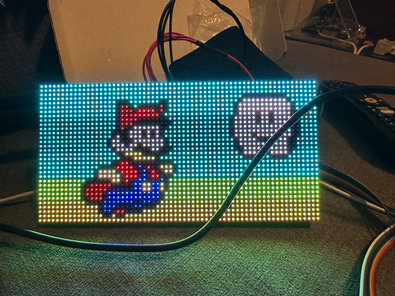
Yessssssss!
But….
There’s a grating flash every 5 seconds as the display corrupts and then redraws. Really annoying. What’s up??
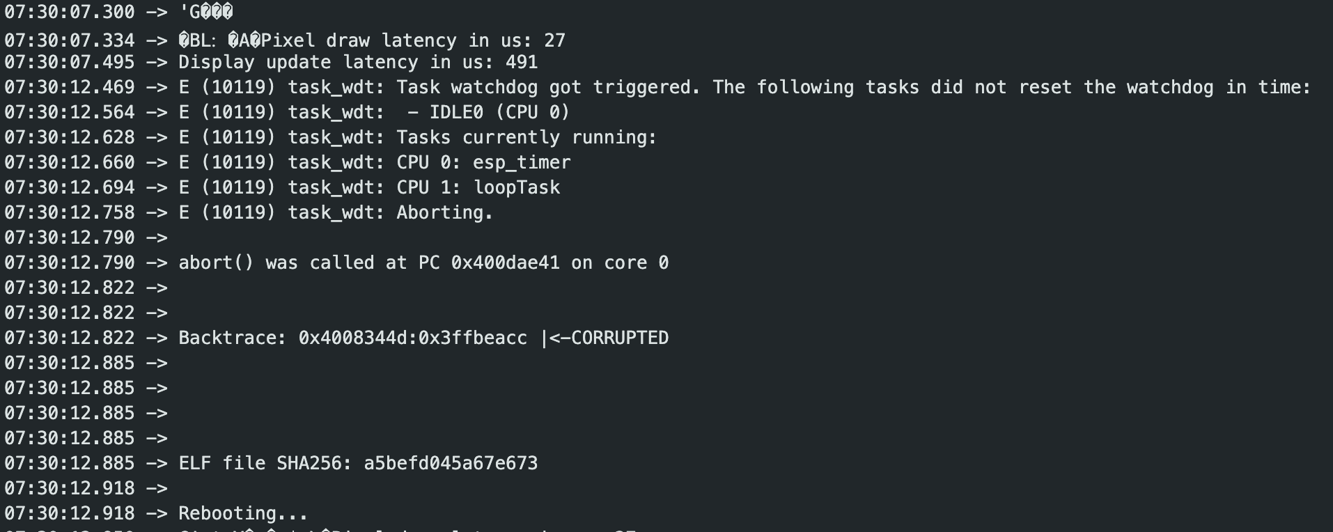
In the Serial Monitor I first saw a brief restart notice, bumping up the logging level to verbose we see the above. A watchdog timer is a task that runs at an interval to verify the main process isn’t crashed, if it’s unable to run or doesn’t get a response within a certain amount of time it restarts the hardware.
In this case it’s basically got a drawing loop that isn’t relinquishing enough for the watchdog and it’s getting killed. The simple fix that worked for me was to refresh less often.
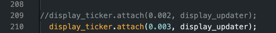
It’s probably due to (as the code mentions), using a really slow drawing method, combined with the high refresh rate it seems to have been running essentially non-stop. Now there’s enough time to breathe and the watchdog timer is happy.
That’s just the way it goes with ported code and random MCUs with different architectures and whatnot. Also older projects tend to “rot” over time as libraries move on and function definitions change. But I got it running and worked out the bugs. Not bad for an evening. Do a random HackerBox once in a while, you’ll be feeling comfortable playing with hardware fairly soon.
Oh. And now I’ve earned the included drink cozy, well done.