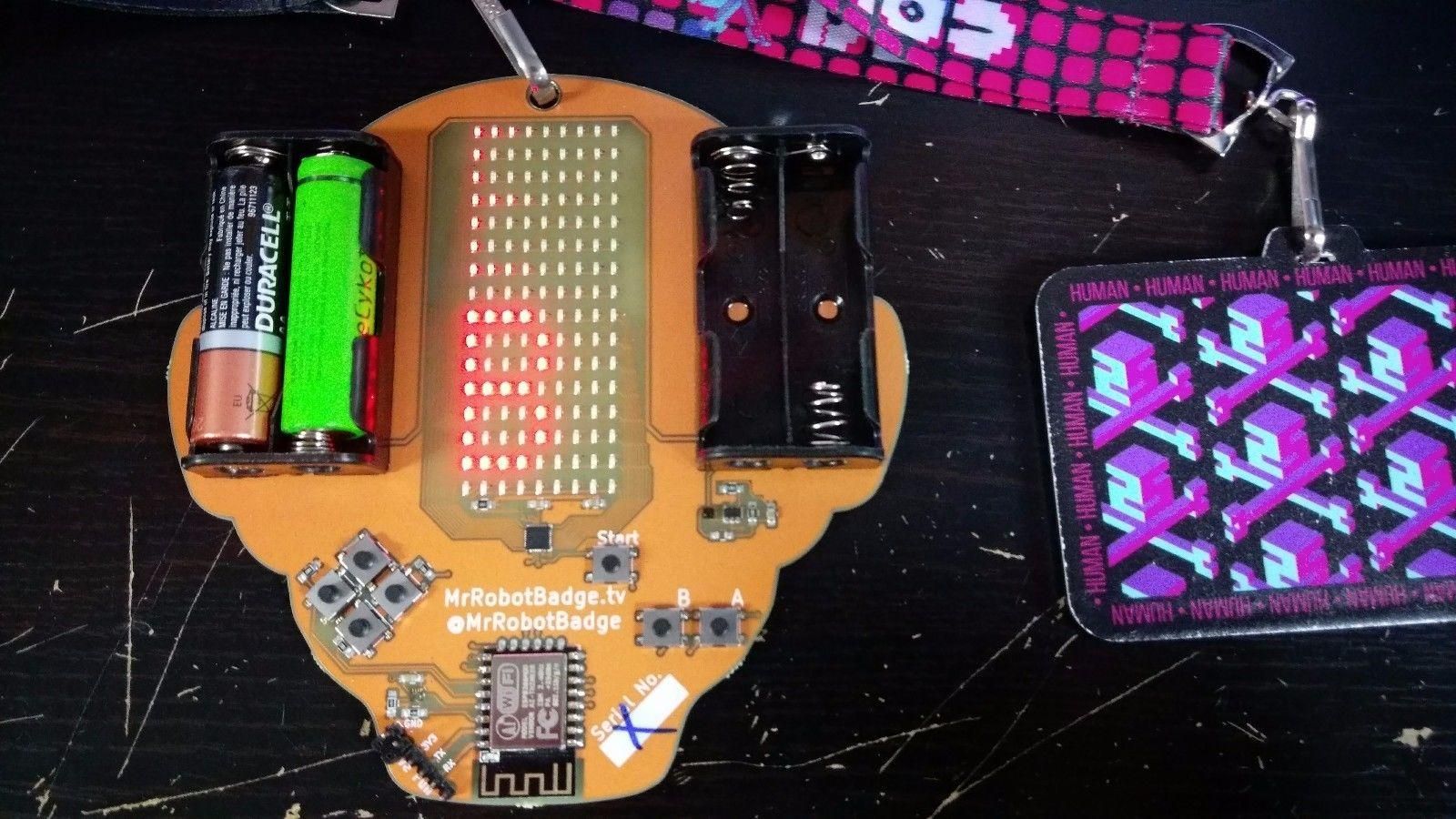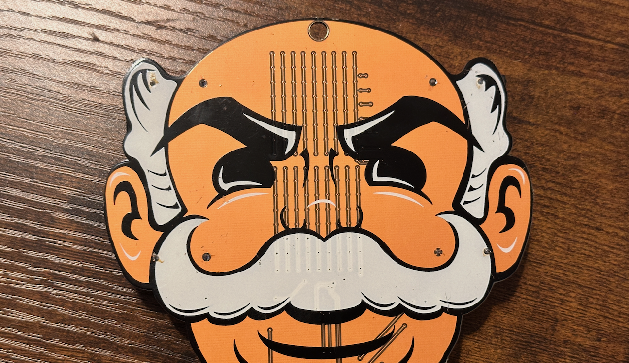
I happened to see an original v1 Mr. Robot badge go up for sale listed clearly defective. Since I already have a v2 and was familiar with it’s design, I figured I’d give it a shot and see if I could get it working.
From the hackaday page the full schematic and firmware BIN file were posted. I figured worst case if there’s damage on the actual PCB traces I could bodge the connections and replace any defective components.
This finally gave me a good excuse to install KiCad and review board files.
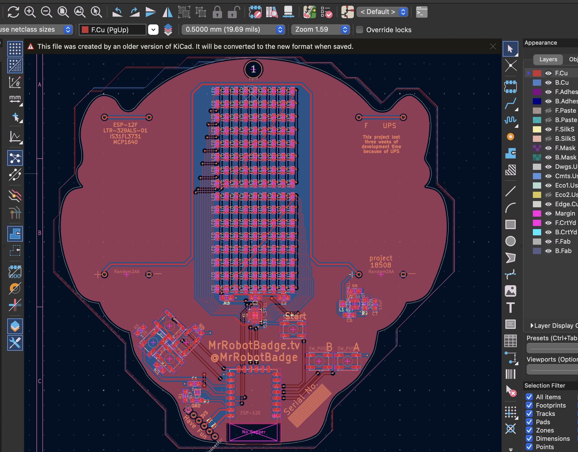
With the electronic schematic showing the logical design, and the board files showing the physical layout I definitely have no excuse not to be able to get this working. 😬
Starting out by examining the board, it would not power on. Though a brief blink of the blue LED on the ESP miniboard showed that some level of power was getting through. I used a multimeter on the VCC and GND pins of the package and saw a weird 1.5v supply. That lead me to testing the battery packs and the power convertor chip.
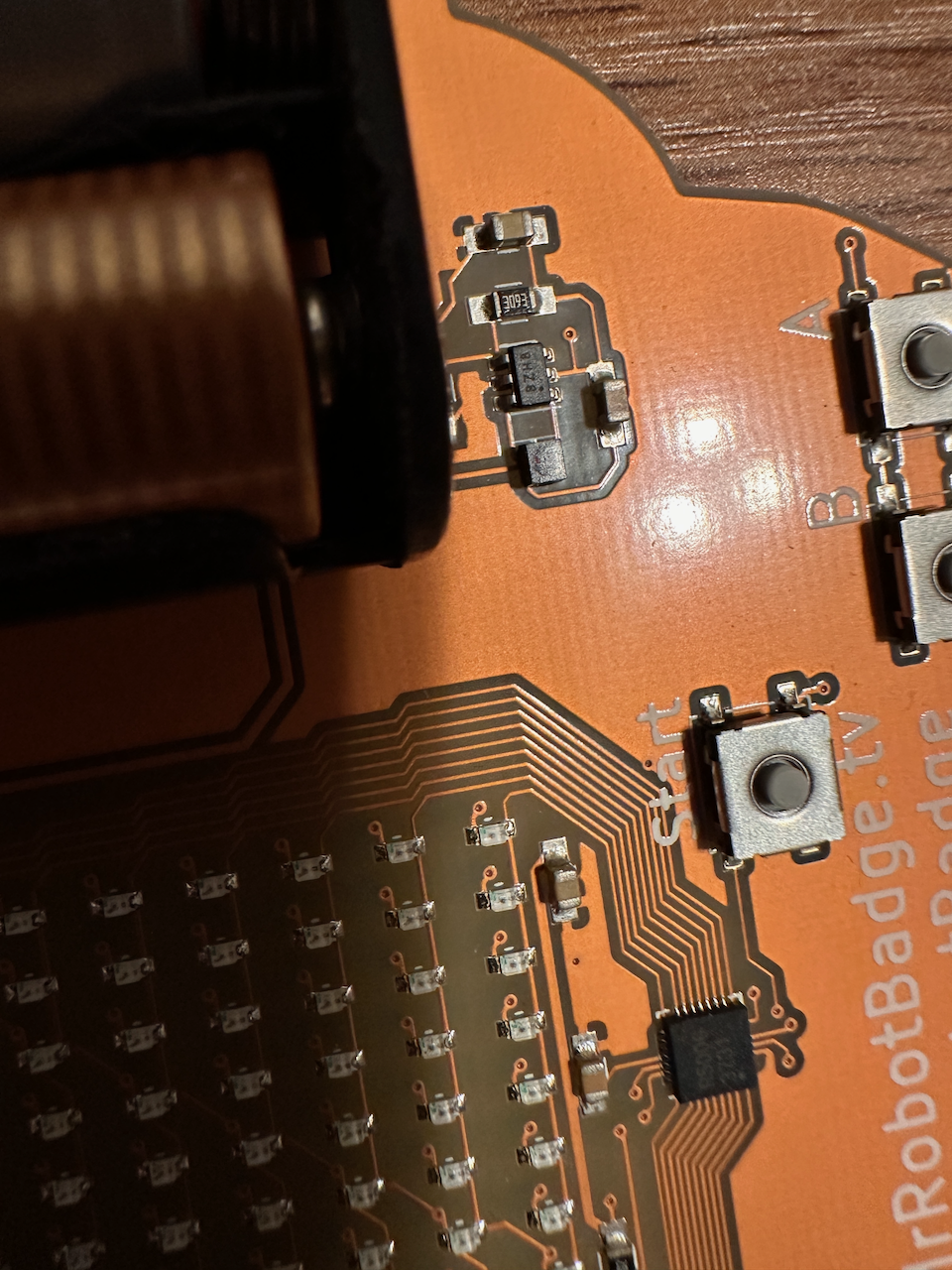
After finding it’s datasheet and identifying pin 1 by the dot you can see there, I verified it was correctly outputting 3.3v and not 1.5v sooo…. what’s the deal? I attempted to power it from the UART pins with a FTDI board set to 3.3v. Though the blue pin lit up, nothing was seen on the serial TX pin at all. Reviewing the code to the v2 board, I noticed they didn’t set up serial output anywhere, so likely the v1 board behaves the same way and is very bare bones with no output while running the badge firmware. So looking for serial output with the screen command isn’t the right approach.
We need to use the ESP tools to test this one. The board however, couldn’t even be identified by esptool. Since I had a flash process example from the v2 Starter Pack page, and the BIN for v1 from hackaday I figured maybe I just needed to flash what was a failed write. But after several attempts the board just wasn’t communicating at all, but some random bytes could get read, no data passing CRC checks came through.
Taking a closer look at the VCC and GND on the ESP8266 board I finally noticed the extremely dry pins and a failed soldering job.
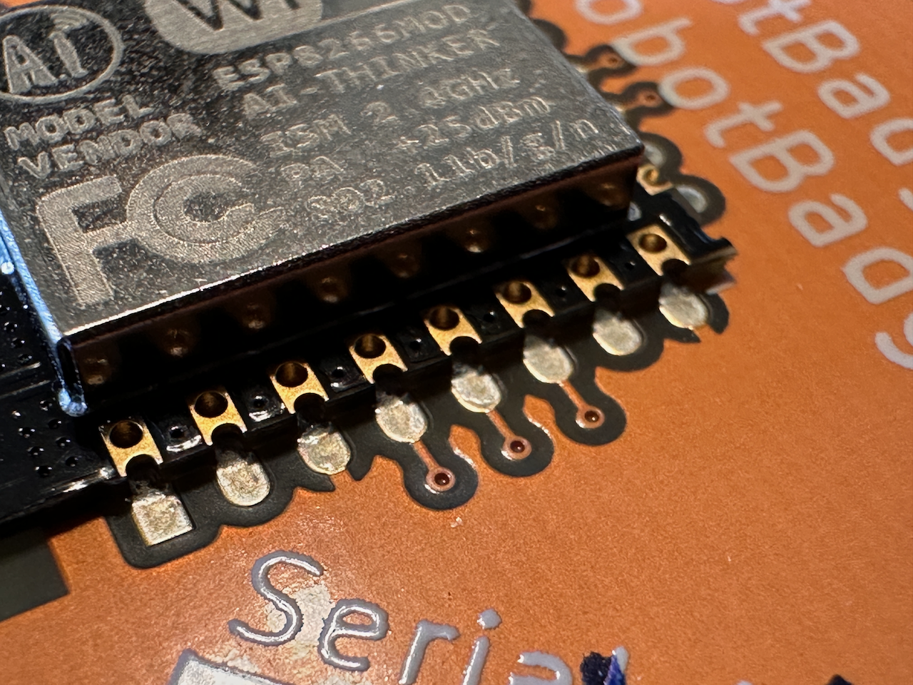
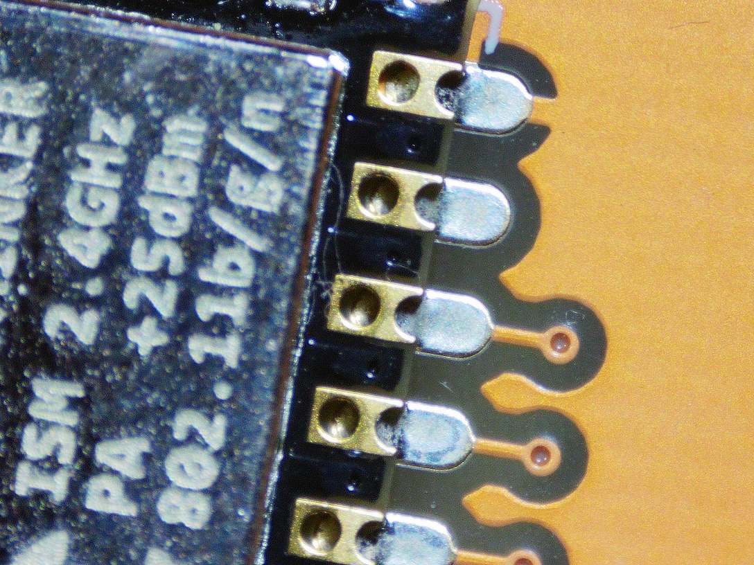 Dry as a bone! 💀
It finally made sense. In the rush to have the boards done in time for defcon, the pogo pin FTDI was used to hold the programmer in place and attempt a write. If the badge booted and showed “Mr Robot Badge”, it got a serial number written on it and went into the “good” box. If it failed to write a couple times…. there wasn’t any time to troubleshoot the badge so it went in the “bad” box for…. I dunno…. disposal? It got an “X” serial number. Maybe they gave them away for free. Update: Some of them took a trip to Supercon!
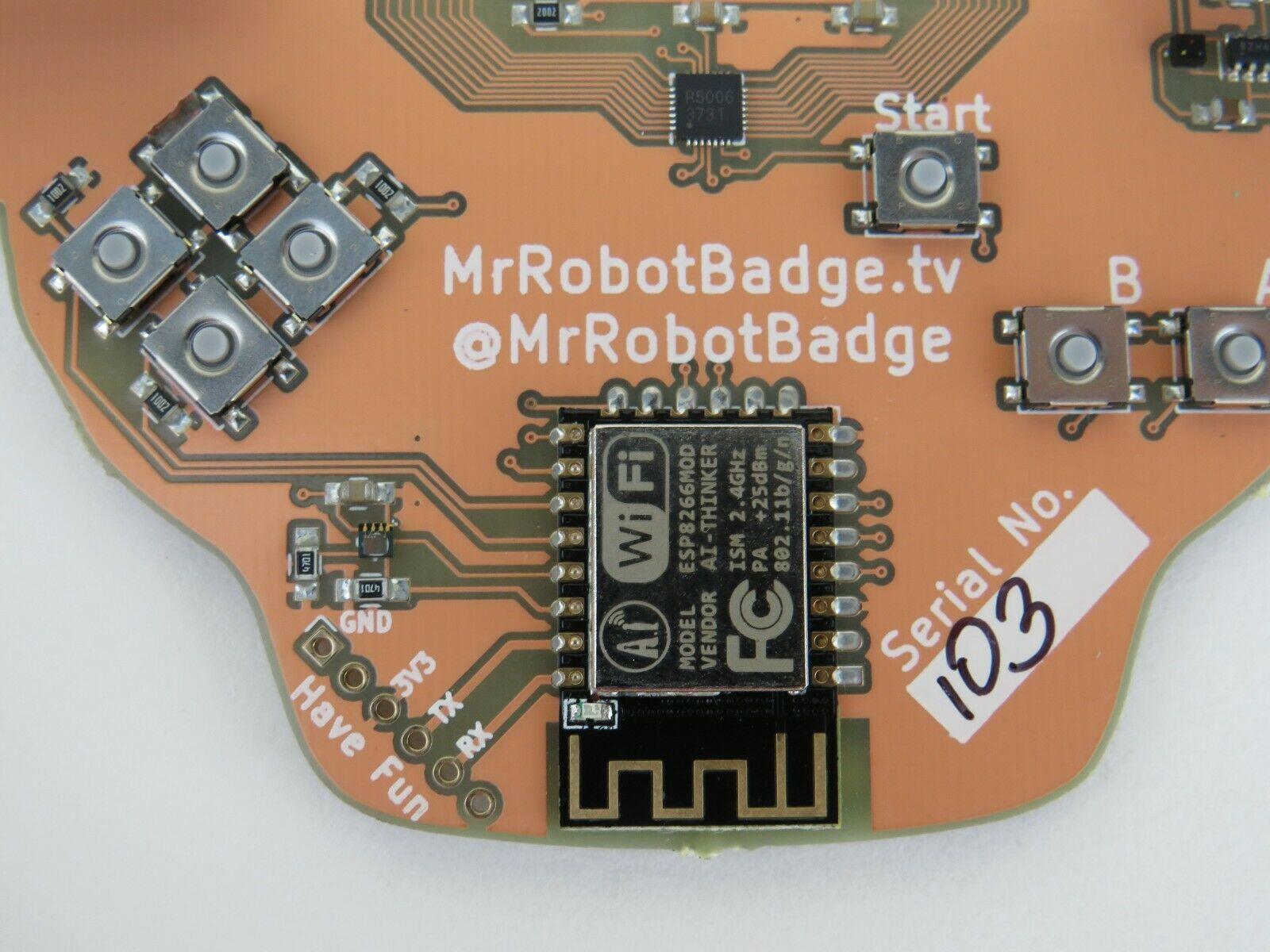
Here’s a valid badge rear… unlike mine:
Time to bust out my new microscope and fix the pins. Almost done!
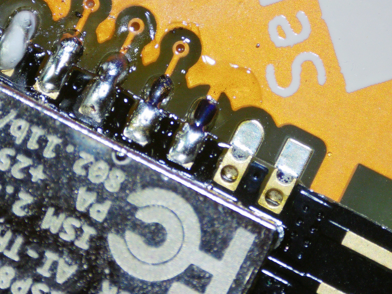
This is sooooooo much better than doing it by eye and occasionally bridging a pin, then wasting hours fixing a rough solder job. Buy a scope. It’s worth it.
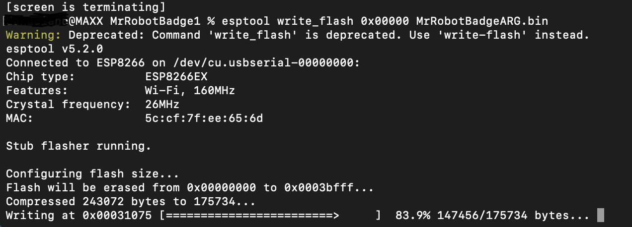
With the pins all cleaned up, the esptool was working correctly and was easily able to write the v1 firmware to the board.
And we are….. GOOD!
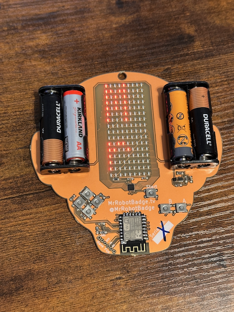
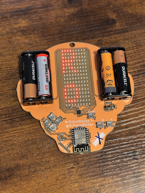
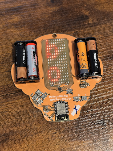
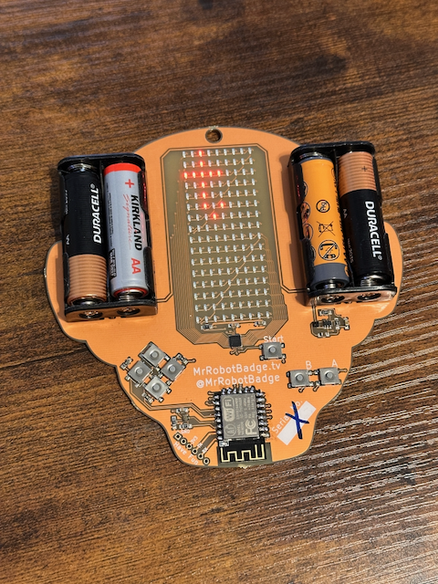
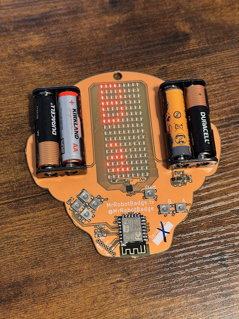
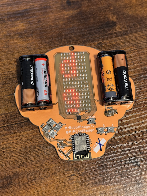
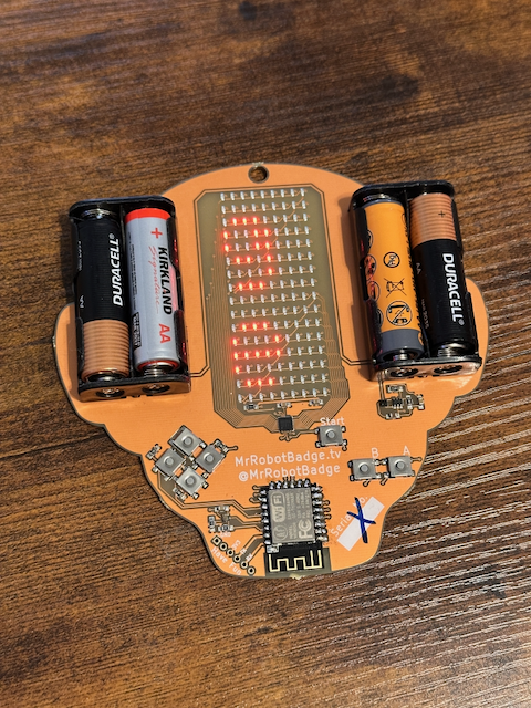
Notice the unique serial “X” on this resurrected badge. 😎
Really glad I took a chance on this one. More board repair in the future…..
Update: Ok so not totally unique. (Archive)