Alright so at the end of part one I showed a complete root and branch image. This requires completing the first four flags and flipping on the first four bits. What was my process? I’m not going to build the badge interaction box, though it’s code and schematic are posted in the Defcon media server. Instead I’m gonna do like on the defcon 20 badge and run my own EEPROM writing code on it.
Since this is an Arduino situation the cross-platform Arduino IDE is the supported tool. You need to install board definition files that fit the dev board you’re using, and library packages to enable using whatever custom hardware your board has. In this case I didn’t see a specific Arduino board mentioned in the docs so I played around and got it working with an Atmel atmega329p Xplained Mini board. This is a little off from the one they used to build, so I’ll run into some issues later.
The Defcon media board files contain the exactly library versions needed for our build. To import the libraries it was a simple matter of zipping each one and doing a manual import.
Now before I completely screw up and brick my badge, it’s worth pulling off the existing firmware and saving it as a backup. Using the steps outlined here and the avrdude in my Arduino app package I was able to get that saved. (Note: save a copy of your archived firmware somewhere else so you don’t accidentally overwrite it while trying to restore your original state. Ask me how I know)
With that done I was finally able to rebuild the INO file and write it to the badge. Let’s reconnect with screen and take a look.
Using the exact same screen command to connect we find….
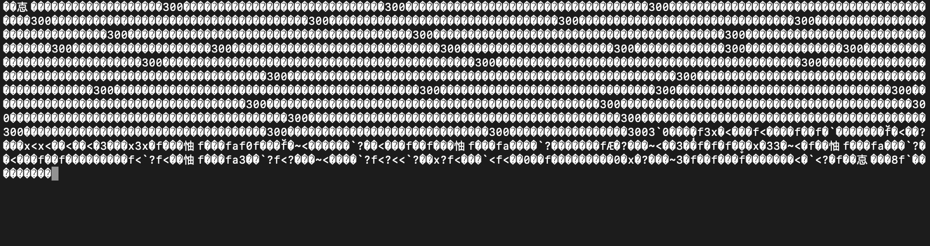
Hrm…. that’s odd. Fortunately I’ve already made this particular mistake plenty of times, it’s a serial console baud rate mismatch, but oddly it’s the same device. What’s going on? Best I can tell at the moment is…. I am using a semi-compatible board for developing, which is setting the clock rate at 4MHz by default, instead of the 8MHz that the badge normally uses.
I’ll see about adjusting that later, for now…. setting the baud at 4800 which is half of 9600 gets us a correctly decoding serial console.
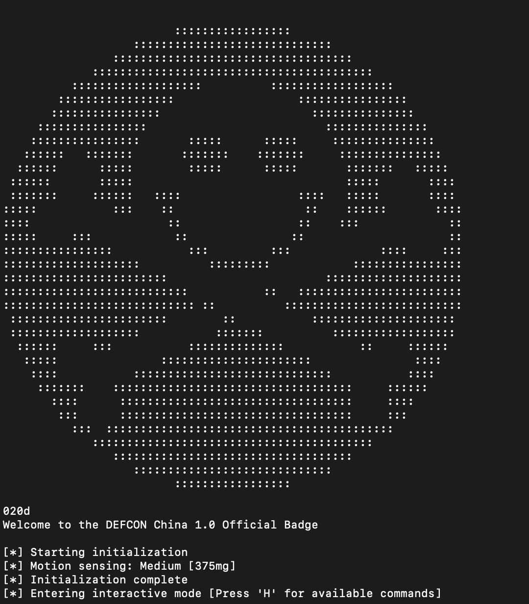
Ok, the 020d text in the output proves we’ve got a working Arduino build of the official source code. W00t!
Here’s setting the last bit with a specific task assigned to it. Does the job.
![]()
In the badge menu there’s a light toggling function we can review the code of to see how things work. LED_All_On lights everything up but it doesn’t persist, also it doesn’t appear to show the animation code so…. let’s write some EEPROM bits!
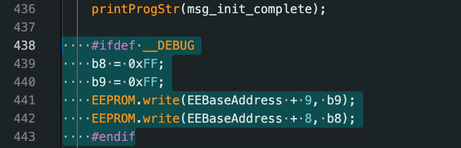
That chunk was added in the setup() function, it runs once on startup and sets all the flags to on. We now have a fully unlocked badge. Check out the animation….
![]()
This video was surprisingly tricky, the LEDs are using PWM to pulse quickly to control their brightness, recording video at 30fps or 60fps makes the video look really different from what a person sees in real life. This is similar to when a video camera passes by an old school CRT TV and has all the flickering. Best thing seems to be using 24fps.
Ok a few interesting tidbits. Whenever it lights up an LED it uses the drawPixel function like so:
matrix->drawPixel(LED_ROOT_1A.x, LED_ROOT_1A.y, LED_ROOT_1A.b);
What’s the .b value doing?
TIL…. if you have a bunch of random LED colors on a board, they’re going to have different brightness levels. This ties directly to the ‘forward voltage’ of the LED, which is the minimum amount before it lights up. Red is the lowest power LED light, then orange, yellow, and in this case green. The code explains it.
// desired brightness for the particular LED color (16 levels)
// different LED colors have different Vf, which affects brightness
// we want all LEDs to visually appear at the same brightness regardless of color
#define LED_BRIGHTNESS_RED      2
#define LED_BRIGHTNESS_ORANGE   6
#define LED_BRIGHTNESS_YELLOW   6
#define LED_BRIGHTNESS_GREEN    12
The lighest reds are nearly as bright as the brightest greens.
Alright another interesting thing. Where’s the loop at?
Here’s the entire tree sparkle animation code.
        // sparkle the branches
        matrix->drawPixel(random(4,8), random(4), random(16));  // set random pixel at random brightness
:|
Huh? Just one line to animate the branches?
Where’s the loop???
The loop is…. the code we had all along. void loop() is one of the 2 main functions, loop checks for a keypress each time the Arduino timer wakes up the chip. It runs through as quickly as it can, then goes back to sleep. Embedded development works a little bit differently than normal procedural code as it’s designed to save power and sleep as much as possible. With 16 branch LEDs and a random value change each loop, a single LED brightness change is happening frequently enough that you get a blinky tree effect without any animation loop at all. It’s also setting all the root LED brightness levels again and again with each pass through. So since I’m running at 4MHz, I actually needed to restore the original firmware to get the tree back to normal speed and see the loop in it’s fully glory.
This makes it tricky to create a custom animation because I must figure out how to set it up in a way that it can work one step at a time without complicated state tracking.
A few approaches:
For simple movement when you have a timer, you can avoid tracking state by abusing modulo math.
Let’s say I want a cyclic movement through a line of 4 LEDs, I can use modulo 4 and any input will result in values from 0-3 in a loop. With some basic logic added, and dividing the timer to get the speed we want…. we can control movement without tracking any state at all.
Looking at the drawPixel command, we see the first parameter is sort of the “Y” of the pixel, which is why the animation only uses values from 4-7, those are the upper LEDs in the branches. Next is sort of the “X” position, but the ends of the branches and roots have a split in them and it’s not exact, but close enough. Then finally the brightness.
If we use modulo to choose our “Y” we can crawl a light up, and setting it for each “X” we can move all branches. The brightness we’ll adjust for style to get a fade or trail effect. If the movement is too fast, we can divide the timer value until we find a stable approximate that only updates once per wake. If we divide by the raw timer value the least significant digit is going to change wildly and the modulo result will appear random.
I did some goofing around with the modulo and the millis() milisecond timer. It worked but the logic was a bit hairy and tricky to control well, so I’ve done a few different animation styles and used another approach to controlling the animation timing. Not sure if anyone actually does that, it’s fairly annoying. Plus randomly jumping about different LEDs makes it hard to figure out what the relative brightness level should be, resulting in the reds being much brighter than the greens in my random blinkie modes.
![]()
It looks better in real life…….. trust me. 😬
Just use a counter and shift behavior for each number range.
I decided to try this one for making the tree lights “grow”. The modulo thing might save some memory and be useful if RAM is extremely tight, but in this case it’s just making it tricky for me to figure out exactly how to control the sequence. Also the LEDs on this tree aren’t in a grid layout physically so lighting up the three highest branch levels in order results in a rotating appearance.
![]()
Here’s another one, this is a ring growing out from the center.
![]()
The other trick is just having a counter byte that I increment with each loop, it automatically wraps itself and is an easy cycle to coordinate the lighting with. Since I now have 4 different badge light animations I wanted an easy way to switch between them without using the keyboard. Finally I have a custom use for the accelerometer chip!
Let’s add a little style. 😎
![]()
Alright kinda silly but I’ve got the badge blink modes chained in a cycle, if you hold the badge upside down and shake it, it detects something in the ballpark of the usual 9.8m/sec/sec acceleration and moves to the next mode in the chain. Now if I’m wearing it and in a mood for a switchup….. no need to plug it into anything or fire up a console. There’s also a hidden ‘g’ function in the badge menu while connected on USB for quick game mode switching.
The acceleration detection was done by a single addition to the interrupt handler, setting change_game_mode to 1. This function gets called anytime there’s movement above a certain threshold. When I see change_game_mode set to 1, I check if the movement was enough to trigger a change. In my case I decided to go with greater than 9.8m/sec/sec while the badge is upside down. That should prevent accidental shifting.
![]()
A neat thing I learned using the accelerometer interrupt function…. make sure it exits quick and doesn’t output anything. When I had a serial output command in there (commented in the previous image line 1580) it was crashing the badge. Partial output could be seen but it would end up frozen. I’m not sure exactly why it crashes but the interrupt is clearly called more than once before the first execution completes and the code being run is not “renentrant” or capable of running two copies without conflict.
So we have the original blink the branches, a similar blink everything mode, a slightly different pulse everything that attempts to move the lights, an inner to outer growing ring animation and finally a growing tree animation.
Part 3 goes into 3d modeling and printing.